
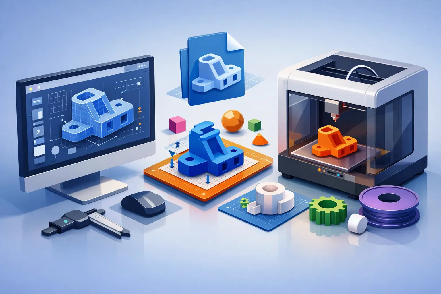
A CAD model can look complete in an engineering review and still create major delays in a rendering, animation, or product visualization pipeline. Hidden components, inconsistent units, overly dense geometry, and unclear assembly names can all turn a straightforward production brief into a round of avoidable questions. Knowing how to prepare CAD files before handoff gives your 3D team the technical foundation to produce accurate visuals faster.
For marketing teams, manufacturers, architects, and production studios, the goal is not simply to send the largest possible file. The goal is to provide a clean, intelligible source model that preserves the product or structure’s intent while allowing artists to optimize it for the final medium. A model for a photoreal product render requires different preparation than one intended for animation, a medical cutaway, or a real-time configurator.
Start with the final production objective
Before exporting anything, define what the CAD data will support. Will the asset appear in still product images, an animated commercial, an architectural walkthrough, technical training content, or a sales presentation? The answer determines how much geometry needs to remain, which surfaces need detail, and whether moving parts need separate pivots.
A still render may only require the exterior surfaces visible to camera. An exploded-view animation, by contrast, needs individual components, logical assembly structure, and enough internal accuracy to show how the product comes apart. If an object will be shown in close-up, details such as seams, fasteners, buttons, vents, and embossed markings should be retained or clearly identified in reference material.
Provide the production team with a short brief that states the intended output, camera priorities, expected level of realism, and non-negotiable design features. This prevents a common mistake: treating CAD geometry as a complete creative brief. CAD explains construction well, but it rarely communicates material finish, lighting intent, or which features matter most to the audience.
Confirm units, scale, and orientation
Scale errors are one of the quickest ways to lose production time. A model exported in millimeters can arrive as an object interpreted in inches or meters. That affects camera setup, light behavior, animation distance, simulation settings, and the relationship between multiple assets in a scene.
Confirm the working units in the source file and state them plainly in the delivery notes. Include one or two known real-world dimensions, such as the overall product width or the floor-to-ceiling height of an architectural model. This gives the 3D artist a simple way to validate the import.
Orientation matters just as much. Establish which direction is front, which axis is up, and where the model origin sits. For products that will rotate on screen, placing the pivot point at a sensible location, often the center of the base or the mechanical hinge, makes animation more efficient. For buildings and large environments, a clean origin near the project center helps avoid precision problems in downstream software.
Organize the assembly before export
A well-structured CAD assembly saves hours of manual sorting. Names such as Part_001, Copy_2, or Final_Final_RevB do not provide enough context for an external production team working against a deadline. Rename major parts and groups using terms that identify both their function and their location.
For example, use names such as front housing, rear mounting bracket, left control knob, or upper glass panel. Organize components into logical assemblies that reflect how the object is manufactured or how it should animate. If a lid opens, a wheel turns, or a mechanism slides, keep those elements separate rather than merging them into a single body.
This structure is especially valuable for product animation and technical visualization. It enables the artist to isolate moving components, assign materials consistently, and create accurate exploded views without rebuilding the assembly hierarchy. For architectural visualization, separate walls, glazing, floors, fixtures, landscaping, and furniture where practical. A single monolithic building model can be usable, but it slows revisions when a client changes one material or design zone.
Remove what will not support the visual result
Engineering models often contain details that are necessary for manufacturing but unnecessary for 3D visualization. Internal threads, tiny screws, hidden brackets, complex fasteners, dense electronics, and microscopic fillets can inflate file size without improving the image or animation.
Clean-up should be deliberate, not aggressive. Remove hidden or irrelevant parts only when they will not appear in the planned shots or affect an animation. Simplify repeated small features when they are too distant to read on camera. For example, a detailed screw thread is rarely needed in a wide product shot, while a visible seam around a premium consumer product may be essential.
The right level of simplification depends on the final use. Medical animation and technical training often require more internal detail than consumer advertising. High-resolution close-ups may require geometry that would be excessive in a standard web video. When in doubt, flag uncertain parts rather than deleting them permanently. Your 3D partner can help determine what should remain as geometry and what can be created more efficiently with textures or normal maps.
Check geometry quality and surface continuity
CAD systems are designed around precise NURBS surfaces and solid bodies, while many visualization and animation applications rely on polygon meshes. During conversion, surface issues can become visible as broken shading, gaps, overlapping faces, faceted curves, or unexpected holes.
Before delivery, check for duplicate components, open surfaces, non-manifold geometry, and intersecting parts that should be separate. Confirm that visible exterior surfaces are watertight where possible. Pay special attention to rounded edges, thin walls, transparent parts, and complex blends, since these areas are more likely to produce conversion artifacts.
Do not assume every edge in CAD should look perfectly sharp in the final render. Real objects catch light along small bevels and rounded edges. If the source model lacks these details because they are too small for engineering purposes, the 3D artist may add render-ready bevels during optimization. This is normal and often necessary for a convincing result, but the underlying proportions should remain accurate.
Use the right file formats and include source files
Native CAD files are often the best starting point because they preserve assembly structure and surface data. Common formats vary by industry, so send the original source file whenever possible, along with a neutral export such as STEP, IGES, Parasolid, SAT, or JT if your workflow supports it.
There is no single best format for every project. STEP is widely used for exchanging solid models and assemblies. IGES can be useful for surface-based data but may require more cleanup. Formats such as FBX, OBJ, or Alembic are more common once the model has entered a polygon-based content pipeline, but they may not retain the precision or hierarchy available in native CAD data.
If your team has already exported a mesh, include the original CAD source as well. A polygon export may be sufficient for a simple render, yet the source file gives the production team more options if geometry must be repaired, re-tessellated, or separated for animation. Package all files in clearly labeled folders and avoid sending only screenshots or a flattened PDF when editable 3D data exists.
Supply visual references and material direction
CAD data defines shape, not appearance. A gray solid model does not tell an artist whether a surface is powder-coated aluminum, matte ABS plastic, brushed stainless steel, frosted glass, or a specific painted finish. Reference images close that gap.
Provide approved product photography, material samples, finish codes, color values, logo artwork, labels, and packaging files where relevant. If the physical product is not yet manufactured, provide industrial design renderings, CMF documentation, and annotated screenshots that identify visible materials. For architecture, include finish schedules, elevations, floor plans, landscape references, and any approved design visuals.
Be specific about brand-critical details. A slight difference in gloss level, wood grain direction, logo placement, or screen content can change how a product is perceived. Clear references reduce subjective review cycles and help the final visuals align with launch requirements.
Document revisions and protect the production schedule
A controlled handoff is more valuable than sending a new file every time a minor change occurs. Identify the revision number, date, and status of every model. State whether the design is final, near-final, or still subject to engineering changes. If a component changes after modeling has started, describe exactly what changed and whether it affects size, placement, materials, or animation.
For larger programs, maintain a simple change log with the updated file package. This gives both internal stakeholders and the outsourced team a reliable record of decisions. It also helps prevent an older CAD version from being used in an approved visual.
At 3D Modeling Animation Studio, an expert production team can assess incoming CAD data, resolve conversion issues, and optimize assets for rendering or animation. The strongest results still begin with a clear, organized handoff that allows artists to focus on visual quality rather than file recovery.
A prepared CAD package does more than shorten import time. It gives every stakeholder a shared technical reference, keeps revision costs under control, and gives your visual production team room to make the work look as precise as the product itself.